
Ultimate Guide to Shear Force and Bending Moment Diagrams Engineer4Free The 1 Source for
Unloaded prismatic beam. Consider an unloaded prismatic beam fixed at end B, as shown in Figure 12.2. If a moment M1 is applied to the left end of the beam, the slope-deflection equations for both ends of the beam can be written as follows: M1 = 2EK(2θA) = 4EKθA (1.12.1) (1.12.1) M 1 = 2 E K ( 2 θ A) = 4 E K θ A.
Beam Bending Equations Moment New Images Beam
Shear force and bending moment diagrams are powerful graphical methods that are used to analyze a beam under loading. This page will walk you through what shear forces and bending moments are, why they are useful, the procedure for drawing the diagrams and some other keys aspects as well. If you're not in the mood for reading, just watch the video!

Brief Information About Shear Force And Bending Moment Diagrams Engineering Discoveries
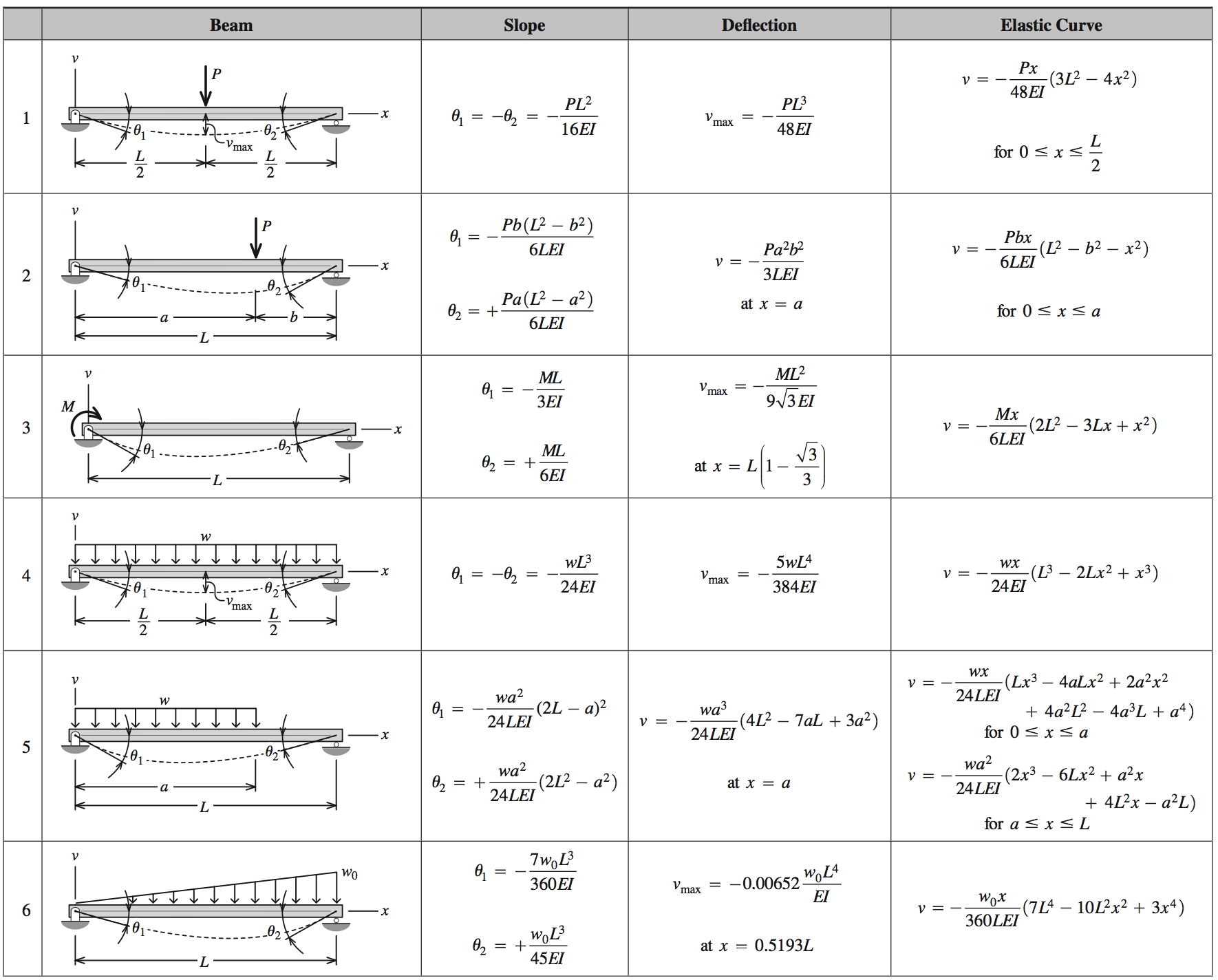
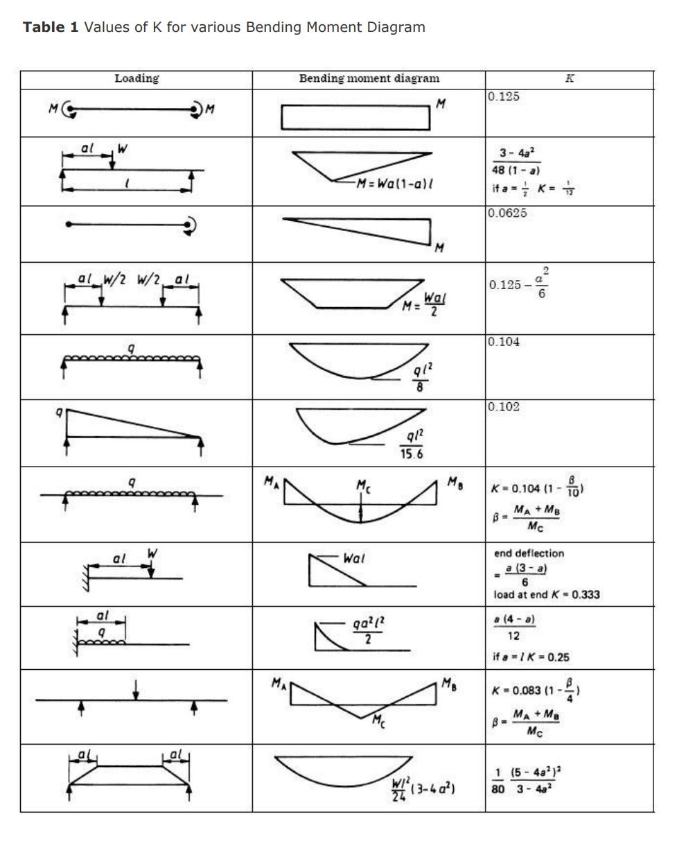
Simply select the picture which most resembles the beam configuration and loading condition you are interested in for a detailed summary of all the structural properties. Beam equations for Resultant Forces, Shear Forces, Bending Moments and Deflection can be found for each beam case shown. Handy calculators have been provided for both metric.

Understanding Shear Force And Bending Moment Diagrams Engineering Discoveries
The bending moment diagram indicates the bending moment withstood by the beam section along the length of the beam. It is normal practice to produce a free body diagram with the shear diagram and the bending moment diagram position below For simply supported beams the reactions are generally simple forces. When the beam is built-in the free.

Shear force & Bending Moment Formulas With Diagram CCAL Shear force, Bending moment, Civil
BEAM GURU .COM is a online calculator that generates Bending Moment Diagrams (BMD) and Shear Force Diagrams (SFD), Axial Force Diagrams (AFD) for any statically determinate (most simply supported and cantilever beams) and statically indeterminate beams, frames and trusses.

Shear force and bending moment diagrams for beams pdf
Shear Force Moment Relationship. Consider a short length of a beam under a distributed load separated by a distance δ x. The bending moment at section AD is M and the shear force is S. The bending moment at BC = M + δ M and the shear force is S + δ S. The equations for equilibrium in 2 dimensions results in the equations..
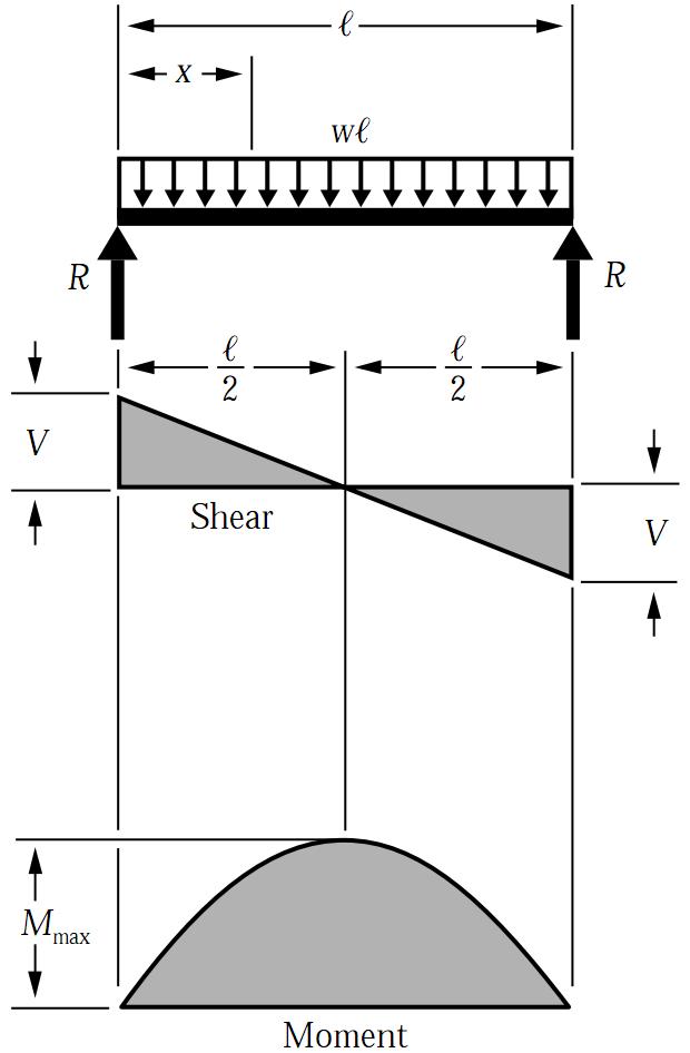
Simply Supported UDL Beam Formulas Bending Moment Equations
Shear and moment diagrams are graphs which show the internal shear and bending moment plotted along the length of the beam. They allow us to see where the maximum loads occur so that we can optimize the design to prevent failures and reduce the overall weight and cost of the structure. Since beams primarily support vertical loads the axial.
moment de force formule
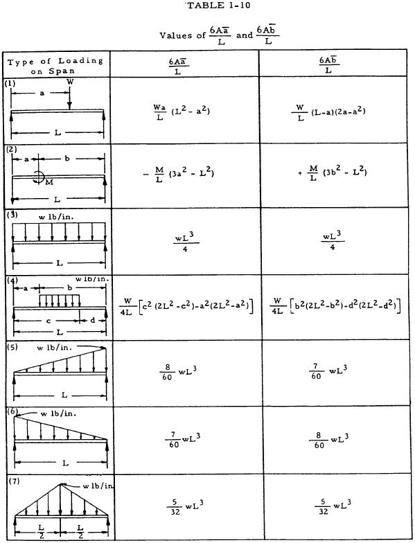
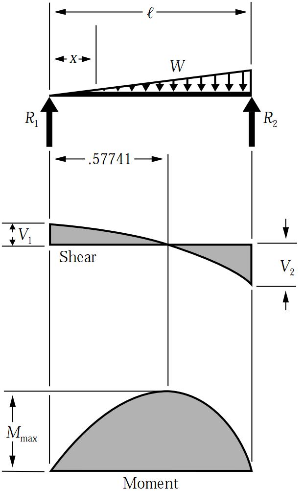
Introduction Figures 1 through 32 provide a series of shear and moment diagrams with accompanying formulas for design of beams under various static loading conditions. Shear and moment diagrams and formulas are excerpted from the Western Woods Use Book, 4th edition, and are provided herein as a courtesy of Western Wood Products Association.

Bending moment formula for beams Design Floor
Calculate shear force diagrams How to use SkyCiv Beam Calculator Welcome to our Free Beam Calculator! Our calculator generates the Reactions, Shear Force Diagrams (SFD), Bending Moment Diagrams (BMD), deflection, and stress of a cantilever beam or simply supported beam.

Learn How To Draw Shear Force And Bending Moment Diagrams Engineering Discoveries
These reactions can be determined from free-body diagrams of the beam as a whole (if the beam is statically determinate), and must be found before the problem can proceed. For the beam of Figure 4: ∑Fy = 0 = −VR + P ⇒ VR = P ∑ F y = 0 = − V R + P ⇒ V R = P. The shear and bending moment at x x are then. V(x) = VR = P = constant V ( x.
8 Images Beam Deflection Formula Table And Description Alqu Blog
or dV dx = − w(x) Equation 4.3 implies that the first derivative of the shearing force with respect to the distance is equal to the intensity of the distributed load. Equation 4.3 suggests the following expression: ΔV = ∫w(x)dx. Equation 4.4 states that the change in the shear force is equal to the area under the load diagram.

How To Draw Shear Force And Bending Moment Diagram Free Wiring Diagram
1. Calculate reactions at supports and draw Free Body Diagram (FBD) If you're not sure how to determine the reactions at the supports - please see this tutorial first. Once you have the reactions, draw your Free Body Diagram and Shear Force Diagram underneath the beam. Finally calculating the moments can be done in the following steps: 2.

Bending Moment Equation For Cantilever Beam With Udl Diy Projects
Being able to draw shear force diagrams (SFD) and bending moment diagrams (BMD) is a critical skill for any student studying statics, mechanics of materials, or structural engineering. There is a long way and a quick way to do them. The long way is more comprehensive, and generates expressions for internal shear and internal bending moment in.
Solved The Minimum Second Moment of Inertia of Beam Section
Bending diagrams are represented with a straight horizontal line right below the beam. This line represents zero. Beneath the line, the bending moment is negative, above the line bending moment is positive. To understand the sign conventions of bending moment and shear forces, consider this article. How to Draw Bending Moment Diagrams?

Shear Force and Bending Moment Formula BraylonldKerr
Figure2:Acantileveredbeam. Free-body diagrams Asasimplestartingexample,considerabeamclamped(\cantilevered")atoneendandsub-jectedtoaloadPatthefreeendasshowninFig.2.
Simply Supported UDL Beam Formulas Bending Moment Equations
A bending moment diagram provides a graphical representation of how bending moment changes along the length of a beam. In this diagram, the horizontal axis (x) typically represents the length of the beam and the vertical axis (y) represents the magnitude and direction of the bending moment.